I had some ESP8266 modules and WS2812 LEDs laying around, that were only collecting dust, so I decided to make a little, maybe useless, project.
It simply shows the average WiFi RSSI by scanning for networks continuously, adding up the RSSIs and dividing them by the number of found networks. Since I’ve used the Adafruit WS2812 library together with the ESP8266 libs for Arduino, I had a prebuilt function, that can be fed with 0-255 to set a color. As the function name ‘Wheel();’ already states, it cycles through the colors in a circle, so we only need around half of that range. After some tests, I found that adding 100 and multiplying the value by 2.2 works quite ok.
So, you say, this is quite boring for such a powerful microcontroller? You’re right! I decided to add an interrupt to the ‘flash’-button, that is on the dev-board and can be used as a normal GPIO-button. Once pressed, the LED will blink as often as many networks have been found. Afterwards it will show the color for the strongest and then for the weakest signal. The purpose of the serial output was actually just for debugging, but I left it there, so you I can still check the values at any time.
After testing it at home, I finally went out in the wild to test it at a place with a huge amount of networks (60+). I figured out, while the LED was blinking, the controller got reset after ~17 blinks. This was done by the watchdog, that couldn’t be turned off at that time (maybe the lib got an update now). So I decided to feed the not-so-cute-litte dog every blink with ‘ESP.wdtFeed();’.
Here is an example video:
And of course the code:
#include "ESP8266WiFi.h"
#include <Adafruit_NeoPixel.h>

#define PIXEL_PIN	14
#define PIXEL_COUNT	1

#define cfact 2.2

Adafruit_NeoPixel strip = Adafruit_NeoPixel(PIXEL_COUNT, PIXEL_PIN, NEO_GRB + NEO_KHZ400);

// function prototypes
uint32_t Wheel(byte);
void wificount_ISR(void);

// global variables
int n = 0, hrssicol = 0, lrssicol = 0;

void setup() {
	pinMode(14, OUTPUT);
	digitalWrite(14, LOW);
	Serial.begin(115200);
	WiFi.mode(WIFI_STA);
	WiFi.disconnect();
	strip.begin();
	strip.show();
	attachInterrupt(digitalPinToInterrupt(0), wificount_ISR, FALLING);
	delay(100);
}

void loop() {
	// number of networks
	n = WiFi.scanNetworks();

	// variables for highest and lowest rssi value
	int hrssi = -120;
	int lrssi = 0;

	// temp. variable for sum of rssi values
	int m = 0;

	if (n == 0) {
		Serial.println("no networks found");
		for ( int i = 0; i < 5; i++ ) {
			strip.setPixelColor(0, 127, 0, 0);
			strip.show();
			delayMicroseconds(200000);
			strip.setPixelColor(0, 0);
			strip.show();
			delayMicroseconds(200000);
		}
	} else {
		Serial.println("-------------------------");
		for ( int i = 0; i < n; i++ ) {
			m += WiFi.RSSI(i);

			// finding highest value
			if ( WiFi.RSSI(i) > hrssi) {
				hrssi = WiFi.RSSI(i);
			}

			// finding lowest value
			if ( WiFi.RSSI(i) < lrssi) {
				lrssi = WiFi.RSSI(i);
			}

			// infos via serial
			Serial.print(i + 1);
			Serial.print(": ");
			Serial.print(WiFi.SSID(i));
			Serial.print(" (");
			Serial.print(WiFi.RSSI(i));
			Serial.print(")");
			Serial.println((WiFi.encryptionType(i) == ENC_TYPE_NONE)?" ":"*");
			ESP.wdtFeed();
		}

		// calulating color value by shifting average rssi up by 100 and multiplying by a factor for spreading out the range
		int rssicol = ( (m/n) + 100 ) * cfact;

		// infos via serial
		Serial.print("high RSSI: ");
		Serial.println(hrssi);
		Serial.print("high RSSI: ");
		Serial.println(lrssi);

		// set color values for ISR
		hrssicol = ( hrssi + 100 ) * cfact;
		lrssicol = ( lrssi + 100 ) * cfact;

		// infos via serial
		Serial.println("-------------------------");
		Serial.print("average RSSI: ");
		Serial.println(m/n);
		Serial.print("color: ");
		Serial.println(rssicol);
		Serial.print("high RSSI color: ");
		Serial.println(hrssicol);
		Serial.print("low RSSI color: ");
		Serial.println(lrssicol);

		// set color finally
		strip.setPixelColor(0, Wheel(rssicol) );
		strip.show();

		Serial.println("");
	}
}

// Input a value 0 to 255 to get a color value.
// The colours are a transition r - g - b - back to r.
uint32_t Wheel(byte WheelPos) {
	WheelPos = 255 - WheelPos;
	if(WheelPos < 85) {
	 return strip.Color(255 - WheelPos * 3, 0, WheelPos * 3);
	} else if(WheelPos < 170) {
		WheelPos -= 85;
	 return strip.Color(0, WheelPos * 3, 255 - WheelPos * 3);
	} else {
	 WheelPos -= 170;
	 return strip.Color(WheelPos * 3, 255 - WheelPos * 3, 0);
	}
}

void wificount_ISR() {
	Serial.println("ISR BEGIN");

	// turn off LED
	strip.setPixelColor(0, 0);
	strip.show();

	delayMicroseconds(500000);

	if (n == 0) {
		Serial.println("no networks found");
	} else {
		// blink n times, where n is number of networks
		for ( int i = 0; i < n; i++ ) {
			strip.setPixelColor(0, 127, 127, 127);
			strip.show();
			delayMicroseconds(150000);
			strip.setPixelColor(0, 0);
			strip.show();
			delayMicroseconds(150000);
			ESP.wdtFeed();
		}

		delayMicroseconds(800000);

		// show color for highest value
		strip.setPixelColor(0, Wheel(hrssicol) );
		strip.show();
		delayMicroseconds(1000000);
		strip.setPixelColor(0, 0);
		strip.show();
		delayMicroseconds(200000);

		// show color for lowest value
		strip.setPixelColor(0, Wheel(lrssicol) );
		strip.show();
		delayMicroseconds(1000000);
		strip.setPixelColor(0, 0);
		strip.show();
		delayMicroseconds(200000);
	}
	Serial.println("ISR END");
}
Since I wanted to have an APRS tracker, that I can use with any radio, but didn’t want to spend a lot of money, I found a project called MicroModem. It uses a R2R resistor ladder for audio output and if you want to add a display, it can even decode AFSK1200 packets. I took the existing APRS library that was developed for this board.
Since I used GPS for another AVR project already, I included the GPS library from Adafruit again.
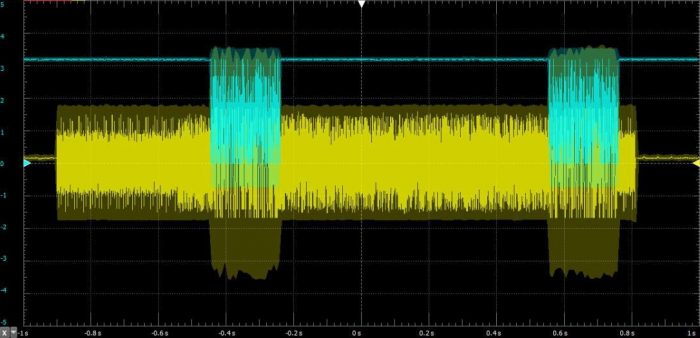
After putting everything together on a breadboard, i did a first test and realized, that the audio was somehow interrupted by something. When commenting out the GPS part of the code, everything worked perfectly… except having a hard coded position. So it was time to hook up the oscilloscope to the audio out pin and the GPS RX pin.
yellow: audio | blue: gps serial data
You can see, that the parser for the received NMEA messages is clearly slowing down the audio, when a messaged comes it, even without using interrupts for parsing. The simpliest solution that came to my mind, was to disable the serial port right before TX function and reactivate again afterwards. This only worked for the first message, but if a second message came in before the transmission stopped, it was interrupted there too. Luckily libAPRS uses an LED, that indicates transmission. So i simply wait for the LED to turn of until I activate the serial port again to avoid delay functions.
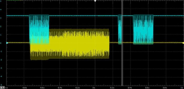
yellow: audio | blue: gps serial data
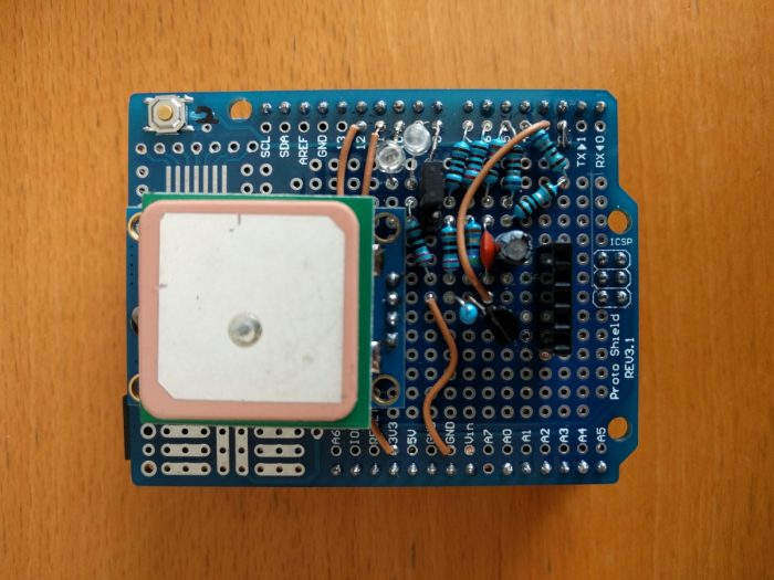
Finally it was working, so I decided to make an Arduino shield for testing it portably, but I want to build a standalone board soon.
I added a jumper to pin 8 to switch between two different APRS SSIDs & symbols for portable and mobile (car) usage. The pinout of the header pins from top to bottom was intended to be audio out, gnd, gnd, PTT, Vin, but sadly my TYT TH-9800 doesn’t provide enough current to power the whole board, so I removed the Vin connection again and power the board over USB, but left the header as it is, in case I need it in the future. The upper left ‘reset’ button was rewired to pin 2 in case i need that too.
I actually wanted to put locationUpdate(); in the ISR, but it doesn’t seem to work inside any ISR, even if I use a timer with a lower priority or disable interrupts while transmitting. However instead of using a delay function or a counter to schedule the transmission, i decided to use the most accurate way – GPS time. Every 30th second of a minute (or any other chosen value) it will transmit audio.
#include <LibAPRS.h>
#include <Adafruit_GPS.h>
#include <SoftwareSerial.h>

// gps serial TX to pin 12
SoftwareSerial gpsSerial(12, 11);

Adafruit_GPS GPS(&gpsSerial);
#define OPEN_SQUELCH false
#define ADC_REFERENCE REF_5V

char lastsec = 0;

void setup() {
  Serial.begin(115200);

  pinMode( 8, INPUT_PULLUP );
  pinMode( 13, OUTPUT );

  APRS_init(ADC_REFERENCE, OPEN_SQUELCH);

  // jumper settings
  if( digitalRead(8) == LOW ){
  // jumper to GND for mobile usage with car symbol
    APRS_setCallsign("NOCALL", 9);
    APRS_setSymbol('>');
  } else {
  // jumper HIGH by internal pullup resistor for portable usage
    APRS_setCallsign("NOCALL", 7);
    APRS_setSymbol('[');
  }

  Serial.println("MicroModem APRS Tracker");
  GPS.begin(9600);
  GPS.sendCommand(PMTK_SET_NMEA_OUTPUT_RMCGGA);
  GPS.sendCommand(PMTK_SET_NMEA_UPDATE_1HZ);
  GPS.sendCommand(PGCMD_ANTENNA);

  // enable tim0 interrupt at value 0x7F
  OCR0A = 0x7F;
  TIMSK0 |= _BV(OCIE0A);

  delay(1000);
  gpsSerial.println(PMTK_Q_RELEASE);
}

// tim0 ISR for gps parser
SIGNAL(TIMER0_COMPA_vect) {
  char c = GPS.read();

  if (GPS.newNMEAreceived()) {
    if (!GPS.parse(GPS.lastNMEA()))
      return;
  }
}

void locationUpdate() {
  char lats[10],latvs[10];
  char lons[10],lonvs[10];

  // the only way i found to set the variables the correct way for libAPRS
  // since sprintf doesn't like float on AVRs
  dtostrf(GPS.latitude, 6, 2, latvs);
  dtostrf(GPS.longitude, 6, 2, lonvs);

  sprintf(lats, "%s%c", latvs, GPS.lat);
  if( GPS.longitude >= 10000 ){
    sprintf(lons, "%s%c", lonvs, GPS.lon);
  } else {
    sprintf(lons, "0%s%c", lonvs, GPS.lon);
  }

  APRS_setLat(lats);
  APRS_setLon(lons);

  char *comment = "Arduino APRS Tracker";

  // turn off soft serial to stop interrupting tx
  gpsSerial.end();

  // TX
  APRS_sendLoc(comment, strlen(comment));

  // read blue TX LED pin and wait till TX has finished (PB1, Pin 9)
  while(bitRead(PORTB,1));

  //start soft serial again
  GPS.begin(9600);
}

void loop() {
  if( GPS.fix ){
    // transmit every 30th second of a minute
    if ( (( GPS.seconds == 30 ) && ( lastsec != GPS.seconds )) ) {
      locationUpdate();
    }
  } else {
    Serial.println("no GPS fix");
    delay(1000);
  }
  lastsec = GPS.seconds;
}

// need to keep that unless i edit libAPRS (fucnt. only needed for rx, but compiler wants it)
void aprs_msg_callback(struct AX25Msg *msg) {
}
I want to mention, that i slightly modified libAPRS to stop the RX interrupts if the ADC gets some floating values. Just comment out the following line in AFSK.cpp: AFSK_adc_isr(AFSK_modem, ((int16_t)((ADC) >> 2) – 128));
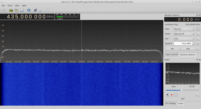
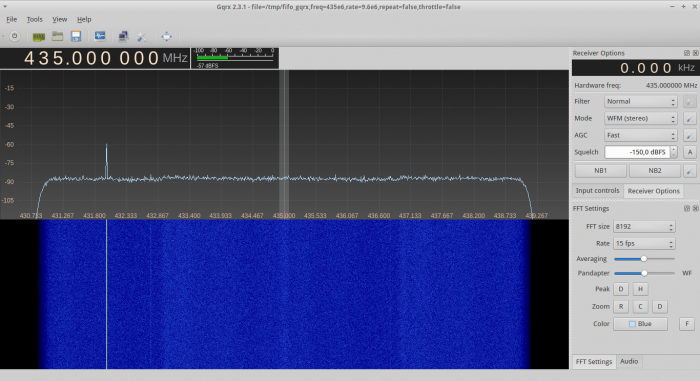
After I managed to combine 2 dongles for an FFT in gnuradio, I wanted to pipe the output to gqrx and add 2 more dongles to the flowgraph. Due to the cut-off at the edges of each dongle, we get 8.4 MHz bandwidth, but since the rational resampler only supports integer values, our sample rate is 4*2.4e6 = 9.6. Use interpolation=35 and decimation=10 for the true sample rate of 8.4 MHz. I updated the 8.4 MHz flowgraph at the bottom of the page.
You can even listen to analog signals, that are at the overlapping areas!
8.4 MHz sample rate:
9.6 MHz sample rate (8.4 MHz bandwidth) with old flowgraph:
At first you need to create a fifo file with this command: mkfifo /tmp/fifo_gqrx
Use this settings in gqrx (change ‘freq’ to the value of center_freq in grc): file=/tmp/fifo_gqrx,freq=100e6,rate=9.6e6,repeat=false,throttle=false
Also make sure, that you set the center frequency in gqrx.
You might have to open gqrx some times if it crashes on startup, but it will work!
Here are the grc-files (right click, save file as):
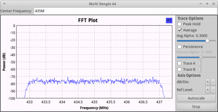
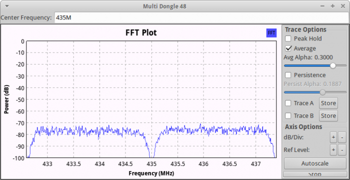
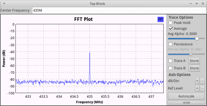
A while ago, I had the plan of taking 2++ RTL2832U SDR dongles to get a wider spectrum in a FFT-plot. Since I had no idea of gnuradio-companion then, I didn’t know how to do this. But thanks to my purchase of a HackRF One, I was forced to use GRC and found some very useful tutorials about SDR in general, with special attention to the HackRF One. You can find the lessons by Michael Ossmann here: http://greatscottgadgets.com/sdr/
So, now that I knew a thing or two about gnuradio, I opened an empty flowgraph and this is the final outcome with 4.4 MHz of bandwidth:
I simply took two RTL-SDR dongles at their max. bandwidth of 2.4 MHz, resampled the signals to 4.8 MHz, then shifted the first signal down by 1MHz, the other one 1 MHz up, added them together, divided the combined signal by 2 to lower the noise floor again and finally feed it into a FFT plot.
At first, I tried shifting the signals by 1.2 MHz to get full 4.8 MHz , but I realized, that I had a notch in the center, so I reduced the frequency shift until I had no notch anymore.
Compared to the HackRF One at 4.8 MHz sampling rate:
Notice, that this isn’t any useful to decode or demodulate any signals, because of phase and clock misalignment, but it can be very handy, if you want to view a larger spectrum than 2.4 MHz and don’t want to spend money in a more expensive SDR, that can be used at higher sampling rates.
If you want to check out the flowgraph or edit it for even more RTL-SDRs, feel free to download it here:
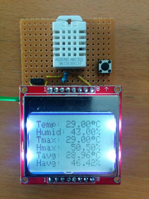
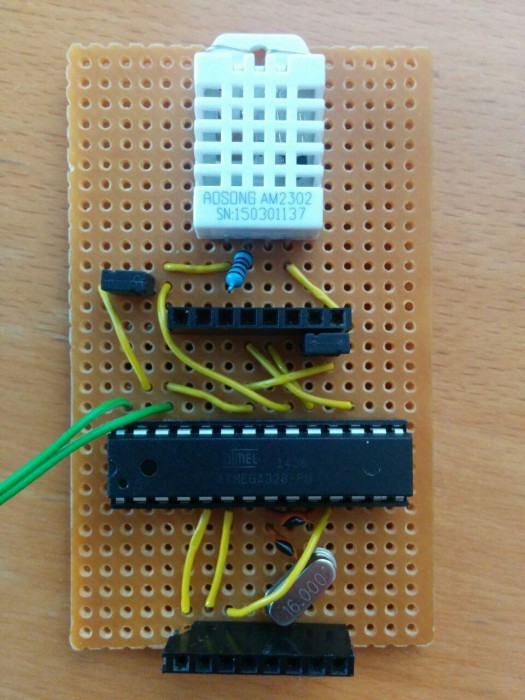
Nachdem die Bauteile herumgelegen sind, habe ich mich dazu entschlossen ein Thermo-/Hygrometer mit einem Atmega328 und Nokia 5110 LCD zu bauen, das mir auch Durchschnitts-, Minimal- und Maximalwerte anzeigen soll.
Der Jumper links oben ist zum ein-/ausschalten; der rechts unter der oberen Steckleiste ist für die Hintergrundbeleuchtung. Um die Beleuchtung nur kurzzeitig zu betätigen, habe ich nachträglich noch einen Taster angebracht, der nur dann etwas bewirkt, wenn der Jumper offen ist.
Der Sensor ist ein AM2302 (auch als DHT22 zu finden). Am Datenpin hängt ein 1k Pull-Up Widerstand.
Auf der Rückseite ist ein AM1117-3.3 angebracht, um das ganze mit einer 9V Batterie speisen zu können.
Der Code kann leicht angepasst werden, um statt der Durchschnittswerte z.B. die Minimalwerte anzeigen zu lassen. Für die Durchschnittswerte wird ein Zähler mit Datentyp ‘unsigned long’ verwendet, wodurch das Programm über knappe 680 Jahre den Durchschnitt berechnen kann, wenn alle 5 Sekunden neue Werte kommen ;)
/*********************************************************************
This is an example sketch for our Monochrome Nokia 5110 LCD Displays

  Pick one up today in the adafruit shop!
  ------> http://www.adafruit.com/products/338

These displays use SPI to communicate, 4 or 5 pins are required to
interface

Adafruit invests time and resources providing this open source code,
please support Adafruit and open-source hardware by purchasing
products from Adafruit!

Written by Limor Fried/Ladyada  for Adafruit Industries.
BSD license, check license.txt for more information
All text above, and the splash screen must be included in any redistribution
*********************************************************************/

#include <SPI.h>
#include <Adafruit_GFX.h>
#include <Adafruit_PCD8544.h>
#include "DHT.h"

// Software SPI (slower updates, more flexible pin options):
// pin 7 - Serial clock out (SCLK)
// pin 6 - Serial data out (DIN)
// pin 5 - Data/Command select (D/C)
// pin 4 - LCD chip select (CS)
// pin 3 - LCD reset (RST)
//Adafruit_PCD8544 display = Adafruit_PCD8544(7, 6, 5, 4, 3);

// Hardware SPI (faster, but must use certain hardware pins):
// SCK is LCD serial clock (SCLK) - this is pin 13 on Arduino Uno
// MOSI is LCD DIN - this is pin 11 on an Arduino Uno
// pin 5 - Data/Command select (D/C)
// pin 4 - LCD chip select (CS)
// pin 3 - LCD reset (RST)
Adafruit_PCD8544 display = Adafruit_PCD8544(5, 4, 3);
// Note with hardware SPI MISO and SS pins aren't used but will still be read
// and written to during SPI transfer.  Be careful sharing these pins!

#define NUMFLAKES 10
#define XPOS 0
#define YPOS 1
#define DELTAY 2

#define DHTPIN 2
#define DHTTYPE DHT22

DHT dht(DHTPIN, DHTTYPE);

float hsum=0,havg=0,tsum=0,tavg=0,tmax=0,tmin=0,hmax=0,hmin=0;
unsigned long n=1;

void setup()   {
  Serial.begin(9600);
  dht.begin();
  display.begin();
  display.setContrast(55);
}


void loop() {
  display.clearDisplay();

  char lcdDegC = char(247);

  if(n==1){
    float hmax = dht.readHumidity();
    float tmax = dht.readTemperature();
    float hmin = dht.readHumidity();
    float tmin = dht.readTemperature();
  }

  float h = dht.readHumidity();
  float t = dht.readTemperature();

  if(h > hmax){
    hmax = h;
  }

  if(t > tmax){
    tmax = t;
  }

  if(h < hmin){
    hmin = h;
  }

  if(t < tmin){
    tmin = t;
  }


  hsum += h;
  havg = hsum / n;

  tsum += t;
  tavg = tsum / n;

  display.setTextSize(1);
  display.setTextColor(BLACK);
  display.setCursor(0,0);
  display.print("Temp: ");
  display.print(t);
  display.print(lcdDegC);
  display.println("C");

  display.print("Humid: ");
  display.print(h);
  display.println("%");

  display.print("Tmax: ");
  display.print(tmax);
  display.print(lcdDegC);
  display.println("C");

  display.print("Hmax:  ");
  display.print(hmax);
  display.println("%");

  display.print("Tavg: ");
  display.print(tavg);
  display.print(lcdDegC);
  display.println("C");

  display.print("Havg:  ");
  display.print(havg);
  display.println("%");

  display.display();
  n++;
  delay(5000);
}
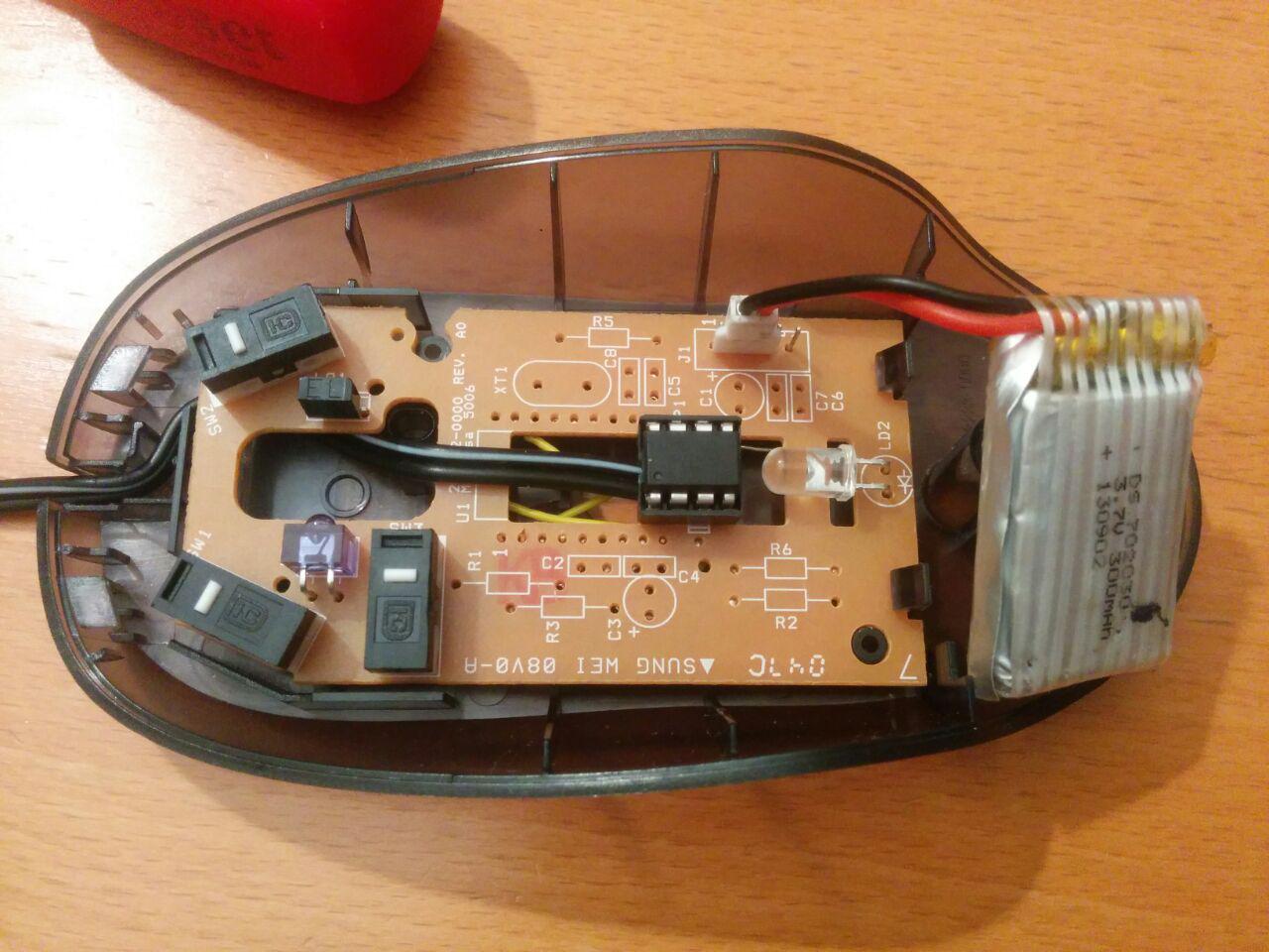
Nachdem ich eine Morsetaste bauen wollte, habe ich mir überlegt, wie ich das am einfachsten anstelle und dazu einfach eine alte Maus genommen. Als Microcontroller wird ein ATtiny85 verwendet und der Akku ist ein normaler Li-Ionen Akku.
Um mögliche Probleme zu vermeiden, habe ich von der Platine der Maus alle Teile abgelötet und anstelle des Sensors den μController angebracht.
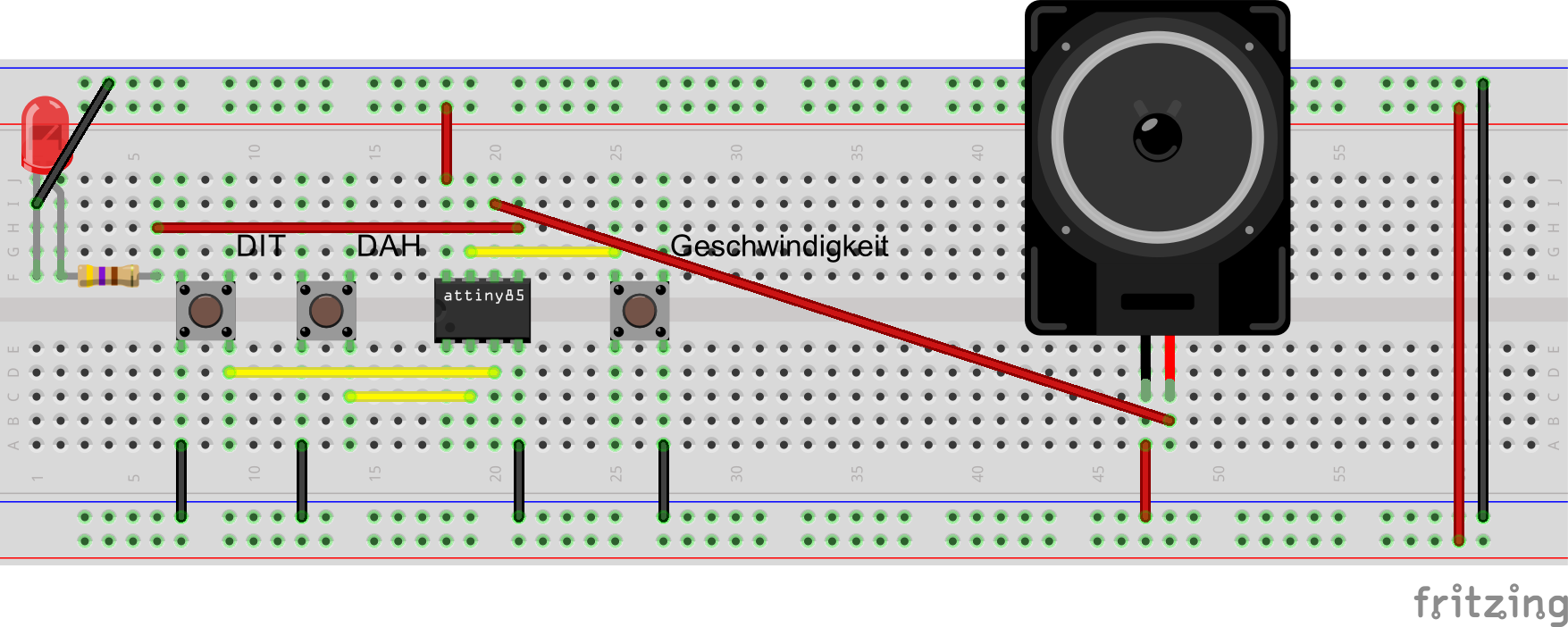
Durch drücken der linken Maustaste wird repetitiv der Punkt ausgegeben und bei der Rechten der Strich. Mit der mittleren Maustaste kann man die Geschwindigkeit ändern, allerdings (noch) nicht über das Mausrad. Es gibt hier 8 Modi.
Der ausgegebene Ton ist ein Rechteckssignal, das durch HIGH-/LOW-Schalten des Pins erzeugt wird.
const int buttonDit = 4;
const int buttonDah = 3;
const int buttonWPM = 2;
const int beepout =  1;
const int ledPin = 0;
int i=0,j=0,k=1;

int dit = 100;
int dah = 300;

const int hper = 715; //halbe periodendauer des tons in mikrosekunden

void setup() {
  pinMode(beepout, OUTPUT);
  pinMode(buttonDit, INPUT_PULLUP);
  pinMode(buttonDah, INPUT_PULLUP);
  pinMode(buttonWPM, INPUT_PULLUP);
  pinMode(ledPin, OUTPUT);
  digitalWrite(ledPin, LOW);
}

void loop() {
  if (digitalRead(buttonDit) == LOW) {
    ditdah(dit);
  }
  else {
    beep(0);
    digitalWrite(beepout, LOW);
  }
  if (digitalRead(buttonDah) == LOW) {
    ditdah(dah);
  }
  else {
    beep(0);
    digitalWrite(beepout, LOW);
  }
  if (digitalRead(buttonWPM) == LOW && k <= 8) {
      k++;
      wpm(k);
      for(int l=1; l<=k; l++){
        digitalWrite(ledPin, HIGH);
        delay(200);
        digitalWrite(ledPin, LOW);
        delay(200);
      }
      if(k == 8){
        k=0;
    }
  }
}

void ditdah(int a){
  digitalWrite(ledPin, HIGH);
  for(i=0; i<a; i++){
    beep(1);
  }
  digitalWrite(ledPin, LOW);
  delay(dit);
}

void beep(int a){
  if(a==1){
  digitalWrite(beepout, HIGH);
  delayMicroseconds(hper);
  digitalWrite(beepout, LOW);
  delayMicroseconds(hper);
  }
}

void wpm(int a){
 switch(a){
   case 0: dit = 100;
           dah = 300;
           break;
   case 1: dit = 90;
           dah = 270;
           break;
   case 2: dit = 80;
           dah = 240;
           break;
   case 3: dit = 70;
           dah = 210;
           break;
   case 4: dit = 60;
           dah = 180;
           break;
   case 5: dit = 50;
           dah = 150;
           break;
   case 6: dit = 40;
           dah = 120;
           break;
   case 7: dit = 30;
           dah = 90;
           break;
 }
}
Am Heimweg vom Dienst wieder einmal auf Parkplatzsuche gewesen, wobei ein Gewitter aufkam und ich die Suche ziemlich schnell aufgegeben habe; Location ist der altbekannte Leopoldsberg.
Letzte Woche habe ich mich dazu entschlossen, einen 120er Diafilm zu verknipsen und bin dazu in die Innenstadt gefahren. Dort fiel mir dann auf, dass ich den Belichtungsmesser zuhause vergessen hatte und probierte einfach einmal nach Gefühl die richtigen Einstellungen zu finden, was in dem Fall bis auf ein paar Überbelichtungen (teilweise leider noch verstärkt wegen schlechter Digitalisierung meinerseits) ganz gut gelungen zu sein scheint.
Das größere Problem war, ein Geschäft zu finden, das noch Diafilme entwickelt. Ich ging wie gewohnt in der Schottenfeldgasse ins Cyberlab, wo man mir sagte, dass die Dia(E-6)-Entwicklung seit 1. Mai eingestellt wurde. Also schickte man mich richtung Opernring zu Foto Fayer, die Glücklicherweise noch immer Dias entwickeln.
Am Mittwoch, 6. Juni 2012, läutete mitten in der Nacht mein Wecker und es dauerte ein paar Minuten, bis ich begriff, warum ich den wohl gestellt habe…ach ja, der Venustransit! :)
Nachdem ich mich fertig gemacht habe, ging es direkt zum Haus des Meeres, das extra für dieses Ereignis die Dachterrasse schon in der Nacht geöffnet hat. Im 9. Stock angekommen wurde einmal das gesamte Kameraequipment ausgepackt und aufgestellt. Gegen 4:55 blinzelte die Sonne erstmals zwischen zwei Kirchtürmen durch:
Wie die Sonne dann schon weiter aufgestiegen ist, habe ich schnell bemerkt, dass das nicht wirklich etwas wird mit eine 18-135mm Objektiv. Zum Glück hatte ein Freund ein nettes Teleobjektiv mit, das für gute Aufnahmen sorgte.
Hier sind gegen 5:15 die Venus und einige Sonnenflecken schon deutlich zu erkennen, aber noch immer atmosphärisch bedingt verschwommen:
Um ca 5:35 gab eine Wolkenschicht der Sonne eine horizontale Struktur:
Nachdem die Sonnen dann schon ziemlich hoch am Himmel stand, konnte man alle Details genau erkennen:
Und zu guter Letzt noch der 3. Kontakt vor dem Austritt:
Ich habe noch 2 Videos gemacht, die den Durchgang zeigen
das zweite zeigt den 3. Kontakt inklusive Austritt (beide sind in Full HD Auflösung betrachtbar)